EPOCH6
Member
Re-post from the other forum, may as well be available here too.
Finally got around to wiring up an ABS switch for my base model 2019 FTR 1200. There are a number of ways to go about doing this, the way I'm doing it is probably the simplest and a fairly typical solution for bikes with non-switchable ABS.
This will, of course, cause your ECU to throw a few codes every time you flip the ABS switch. The codes will go away when you return the switch to the fused position. If check engine lights and error codes and warranties keep you up at night then don't dick around with your wiring. Error codes below:
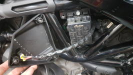
SPN: 65557
FMI: 22
SPN: 65557
FMI: 23
SPN: 520322
FMI: 22
Oddly enough, none of the above codes are listed in the Service Manual nor are they searchable on Indian's website. I'll take that as a good sign, because it means that none of these codes correspond to any of the terrifying situations described in the Service Manual. Out of sight and out of mind... right?
You can flip the ABS Switch at any speed while riding and it works as expected, you do not need to stop moving or shut off the engine at any point. The Error Code light and ABS light will toggle on and off every time you flip the switch, the Check Engine light will go away after a few ABS-enabled rides.
Materials:
Tools:
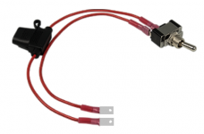
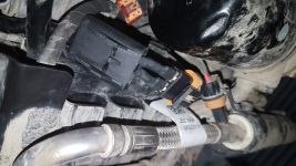
Step 1 - Pull the 25 Amp ABS Valve Fuse:
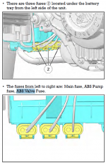
Step 2 - Insert the 25 Amp ABS Valve Fuse into the In-Line Fuse Holder
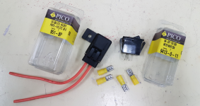
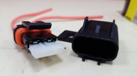
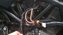
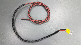
Step 3 - Crimp 2 Female Quick Connectors onto your length of 10 AWG Wire
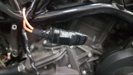
Step 4 - Wrap about 1 ft with Super 88 Electrical Tape
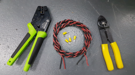
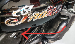
Step 5 - Remove both the Right Side Fuse Box Cover and Left Side Wiring Cover
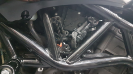
Step 6 - Run your length of wire between the front and rear cylinder, entering the left side of the frame and existing the right side next to the fuse box
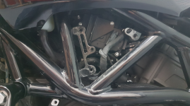
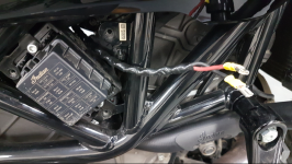
Step 7 - Carve a nasty hole into the Right Side Fuse Box Cover for your Toggle Switch
Make sure you're aware of how much clearance your switch has, the grey line below indicates the edge of the fuse box.
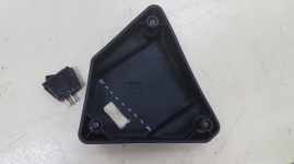
Step 8 - Install your Toggle Switch into the Right Side Fuse Box Cover
I've hit the image limit and will continue this in the following post.
Finally got around to wiring up an ABS switch for my base model 2019 FTR 1200. There are a number of ways to go about doing this, the way I'm doing it is probably the simplest and a fairly typical solution for bikes with non-switchable ABS.
This will, of course, cause your ECU to throw a few codes every time you flip the ABS switch. The codes will go away when you return the switch to the fused position. If check engine lights and error codes and warranties keep you up at night then don't dick around with your wiring. Error codes below:
SPN: 65557
FMI: 22
SPN: 65557
FMI: 23
SPN: 520322
FMI: 22
Oddly enough, none of the above codes are listed in the Service Manual nor are they searchable on Indian's website. I'll take that as a good sign, because it means that none of these codes correspond to any of the terrifying situations described in the Service Manual. Out of sight and out of mind... right?
You can flip the ABS Switch at any speed while riding and it works as expected, you do not need to stop moving or shut off the engine at any point. The Error Code light and ABS light will toggle on and off every time you flip the switch, the Check Engine light will go away after a few ABS-enabled rides.
Materials:
- 3 to 4 ft of 10 AWG wire
- 30 Amp Standard In-Line ATO Fuse Holder, Waterproof
- 12 Volt 20 Amp (or more) On-Off Toggle Switch
- 10-12 AWG Female Quick Connect, Insulated Crimp Terminals
- 10-12 AWG Male Quick Connect, Non-Insulated Crimp Terminals
- 10-12 AWG Insulated Butt Connectors
- Solder / Flux (optional)
- Heat Shrink
- Scotch 3M Super88 Electrical Tape (or any flame-retardant electrical tape rated for at least 105°C)
- Scotch 3M 130C Rubber Splicing Tape (optional, for waterproofing)
- 2 part Epoxy or Silicone
Tools:
- Crimpers
- Wire Strippers
- Wire Cutters
- Zip Ties
- Knife
- Soldering Iron (optional)
- Dremel
- Drill
- Metal Files
- Heat Gun or Lighter

Step 1 - Pull the 25 Amp ABS Valve Fuse:

Step 2 - Insert the 25 Amp ABS Valve Fuse into the In-Line Fuse Holder


Step 3 - Crimp 2 Female Quick Connectors onto your length of 10 AWG Wire
Step 4 - Wrap about 1 ft with Super 88 Electrical Tape


Step 5 - Remove both the Right Side Fuse Box Cover and Left Side Wiring Cover
Step 6 - Run your length of wire between the front and rear cylinder, entering the left side of the frame and existing the right side next to the fuse box


Step 7 - Carve a nasty hole into the Right Side Fuse Box Cover for your Toggle Switch
Make sure you're aware of how much clearance your switch has, the grey line below indicates the edge of the fuse box.

Step 8 - Install your Toggle Switch into the Right Side Fuse Box Cover

I've hit the image limit and will continue this in the following post.
Last edited:


